Printed electronics: VFP silver, carbon and dielectric inks
Printed electronics puts conductive and insulating layers on film: membrane switches, printed heaters, antennas and sensors. VFP Ink Technologies makes 13 silver, carbon, dielectric and piezoelectric inks for screen and flexo printing. We offer VFP Ink Technologies inks in Eastern Europe. For the Bectron® silver, carbon and UV-insulator inks ELANTAS discontinued in September 2026, VFP has a grade to trial.
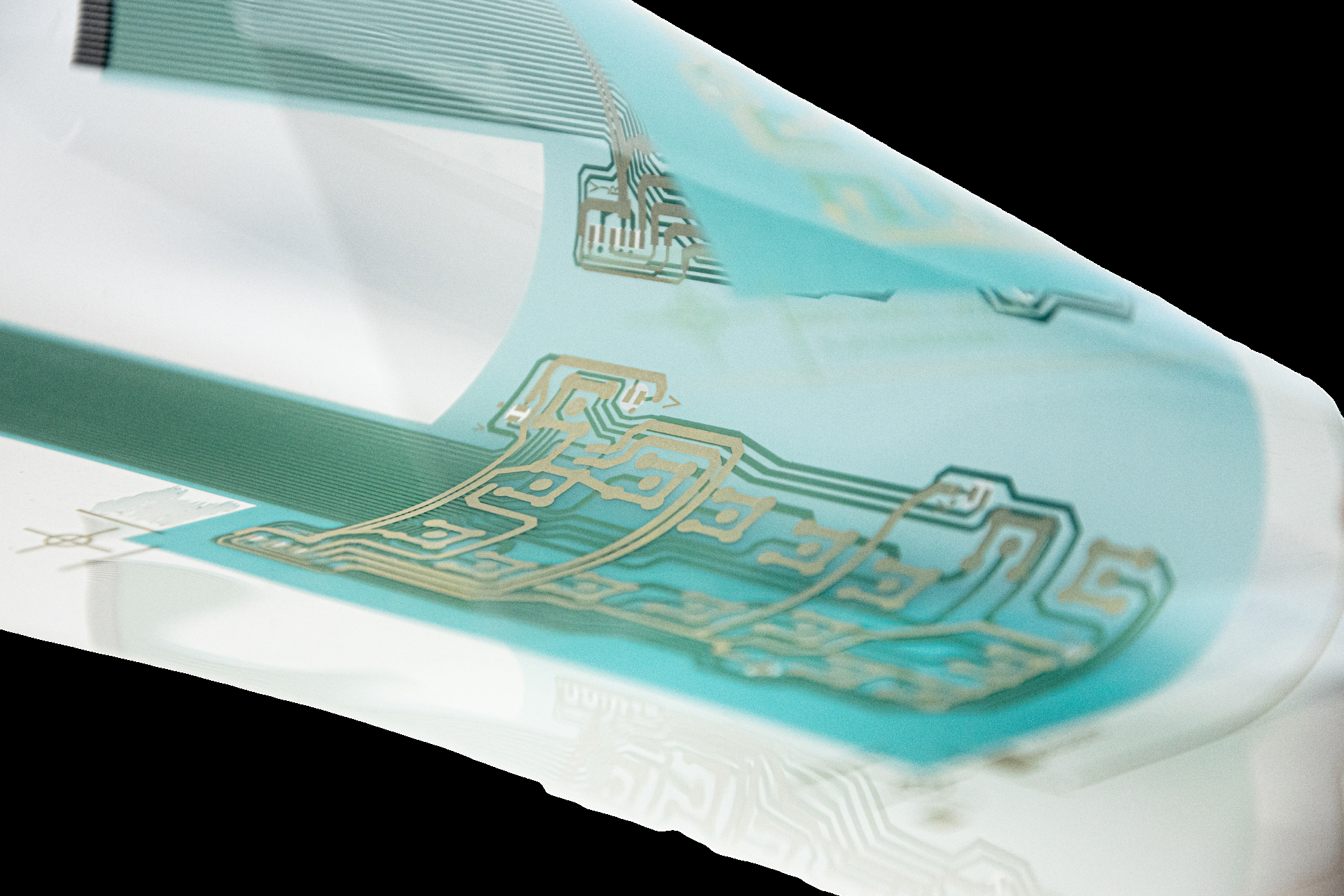
What is printed: silver, carbon and dielectric layers on a substrate
A printed circuit is built by adding ink only where the layout needs a track, a contact or an insulator. VFP lists screen printing as an additive manufacturing method, with “cost effective production”, “quick implementation” and the “possibility to functionalize large surfaces”.
Four kinds of ink build the circuit, each printed as its own layer. Silver carries the current: SE prints tracks at ≤ 15 mΩ/sq/mil. The carbon inks make resistive tracks and protect silver; CEL001 is ≤ 120 Ω/sq/mil. The UV-curing dielectric varnishes insulate, so a second silver layer can cross the first. The piezoelectric inks make printed sensors.
For SE, VFP lists these substrates: paper, cardboard, PVC, PET, polycarbonate, treated polyester, glass and polyimide. Films differ according to their origin, so VFP asks for a preliminary test on yours.
How it is printed: screen printing, mesh and squeegee
All 13 inks print by screen; FSE also prints by flexography. The mesh sets how much ink the screen deposits. For SE, VFP states a mesh of 79 to 120 threads/cm, a polyurethane squeegee of 65 Shore A and a deposit of 8–9 µm from a 90 threads/cm polyester mesh. Tab. 1 gives the mesh for each ink.
SE is printed as delivered: its datasheet says no dilution, and manual shaking before use. On the screen the inks stay printable for 30 minutes to more than 60, depending on the grade.
How it cures: silver and carbon in the oven, the dielectric under UV
The silver and carbon inks cure in your oven at 120 to 150 °C. For several grades VFP also states near-infrared (NIR) lamps, at 2 to 4 s.
| Layer | Example | Cure |
|---|---|---|
| Silver | SE | 30 min at 130 °C or 10 min at 150 °C |
| Silver, low-energy cure | SELEC | 5 min at 120 °C or 3 min at 150 °C; NIR 2 s |
| Carbon | CEL003 | 3–5 min at 120–150 °C; NIR 2 s |
| Dielectric | ECV003, ECV004 | broad-spectrum UV (mercury or xenon), more than 300 mJ/cm² |
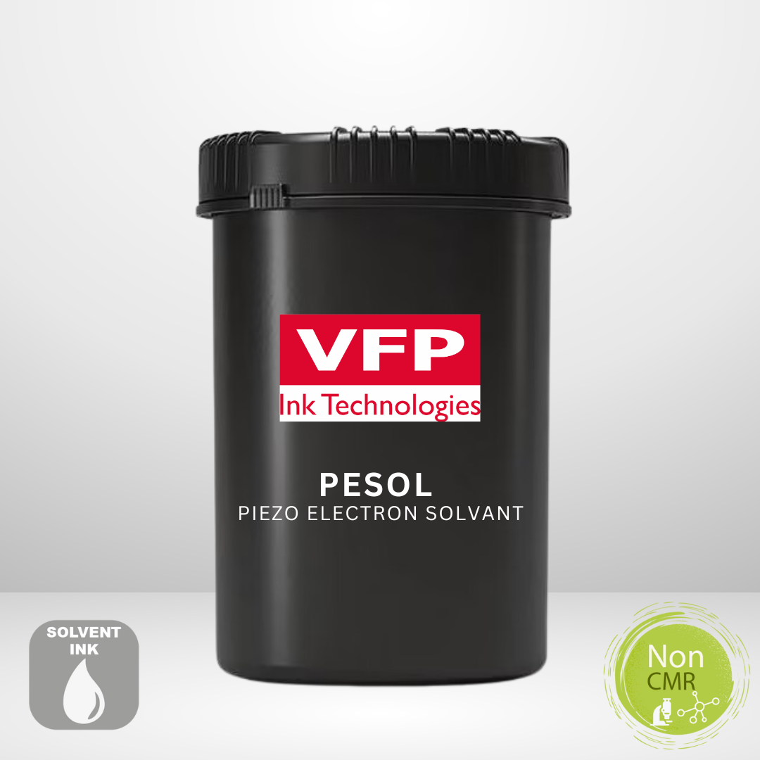
| Piezoelectric | PESOL | 5 min at 120 °C |
VFP dielectrics need broad-spectrum UV. We offer both.
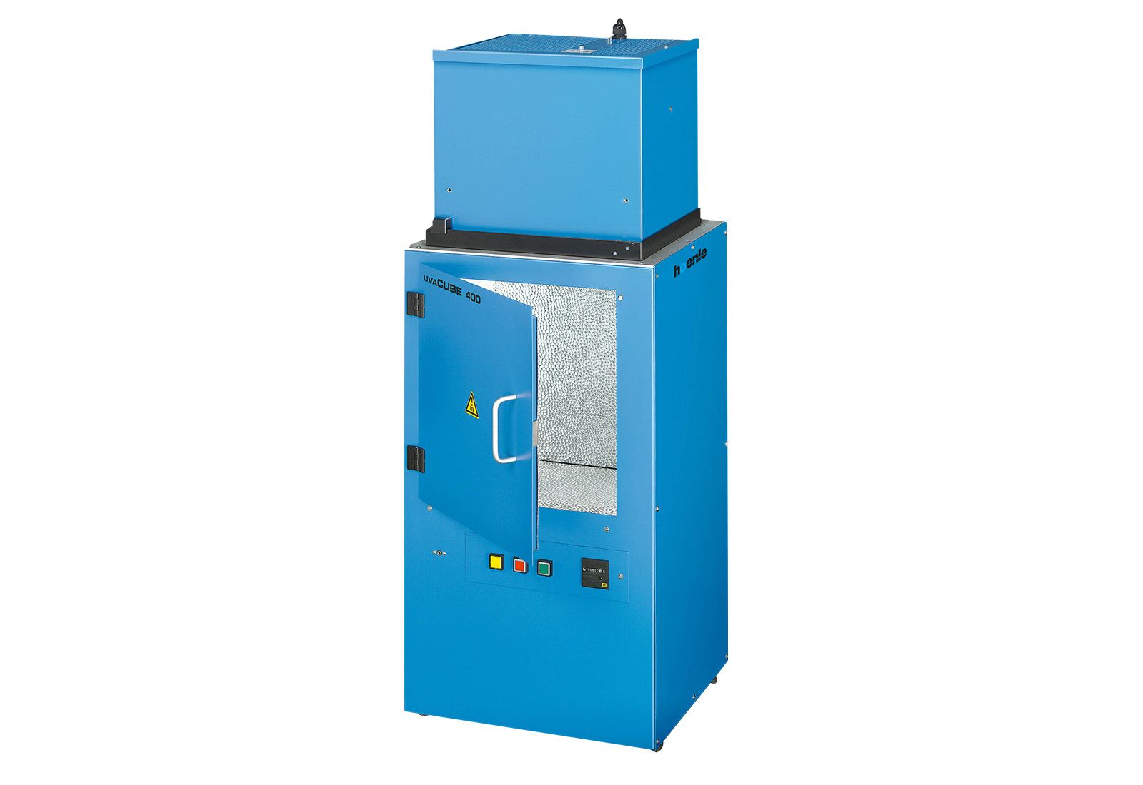
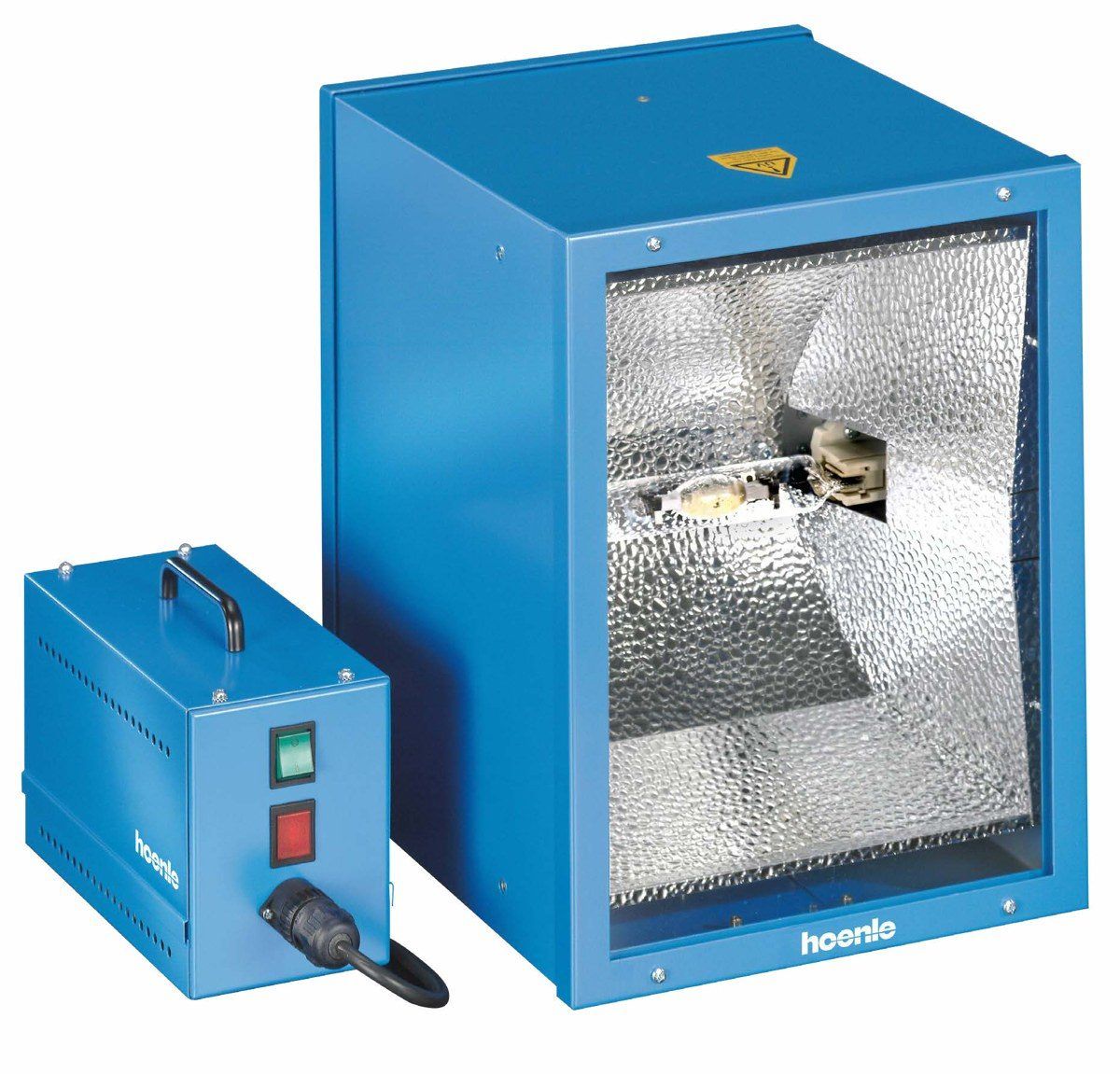
VFP’s two dielectric varnishes, ECV003 and ECV004, cure under a broad-spectrum mercury or xenon UV lamp at more than 300 mJ/cm², with absorption peaks at 359, 365, 380 and 383 nm. They tolerate a higher dose than recommended. Any line that adds a VFP dielectric to silver or carbon work therefore needs a broad-spectrum UV dryer and a way to check the dose.
We offer the VFP inks and the Hoenle AG UV equipment together: conventional (broad-spectrum) UV dryers, chambers and conveyors, replacement lamps, and dose measurement. The Hoenle UV Disc Integrator rides on the conveyor belt and shows the dose in mJ/cm², from 1 to 999,999 mJ/cm² at ± 5 %.
We calculate the dose from lamp, lens, working distance and belt speed and, on request, measure it on site during a visit.
What goes wrong on the line, and what to check first
-
Printed silver track resistance above the calculation
- First cause
- VFP: “Resistance depends on the real substrate, the real dryer profile and the real deposit thickness on your press.”
- Check first
- Whether the oven time is dwell at temperature or time in the oven; the dry thickness; the squeegee and off-contact settings.
-
Carbon track resistance too high
- First cause
- The ink was diluted; dilution “would deteriorate the conductive properties”.
- Check first
- The thinning log on the press; the screen time used; the cure.
-
Ink does not stick to the plastic film
- First cause
- The film’s surface tension; film lots differ according to their origin.
- Check first
- A cross-cut test per EN ISO 2409, target class 0; film cleaning and anti-static.
-
VFP dielectric under-cured under an LED lamp
- First cause
- ECV003 and ECV004 cure under a broad-spectrum mercury or xenon lamp at more than 300 mJ/cm²; VFP states no LED cure for them.
- Check first
- The dose at the sheet with a meter; the lamp’s age.

Which VFP inks for which device
Which VFP inks for which device
Pick a device and read the stack from the film upward: each layer names the VFP ink that prints it. VFP names each of these applications; the ink for each layer is our reading of VFP’s datasheets. Every stack needs a print trial on your substrate, as VFP advises.

- 1SubstratePET
- 2SilverSELEC or LV-SELEC tracks
- 3CarbonCEL003 on the contacts
- 4ECV003 or ECV004 dielectric
With SE tracks, use CEL001.
- 1SubstratePET
- 2SilverSE or SELEC busbars
- 3carbon heating area (CEL001 on SE, CEL003 on SELEC) or an SETF silver track
- 4DielectricECV003 or ECV004 cover
- 1SubstratePET or PC
- 2SilverSE, SELEC or SECTR-I01 electrodes
- 3DielectricECV004 (clear) or ECV003
- 4second silver layer where needed
- 1SubstratePET or paper
- 2SilverFSE by flexography, or SE, SELEC or LV-SELEC by screen
- 3DielectricECV bridge
- 4silver bridge
- 1As the antenna. SECTR-I01 is the grade VFP links to smart labels; the chip is attached in a separate step
- 1SubstratePC film
- 2SES silver
- 3Process stepthermoforming
- 4Process stepinjection moulding
SES is the thermoformable grade.
- 1SubstrateTPU film
- 2SES silver
- 3Process stepencapsulation (a separate material)
- 1SubstratePET
- 2silver bottom electrode
- 3PiezoPEUV or PESOL in 2 passes
- 4silver top electrode
- 5ECV dielectric
- 6Process steppoling
- 1Silver layer 1
- 2DielectricECV003 or ECV004 in 2 passes with via openings
- 3silver layer 2
Check your lamp before you add the dielectric. Which UV dryer, and how to check the dose · Hoenle UV Meter
| Device | Stack, bottom to top |
|---|---|
| Membrane switch or keypad | PET → SELEC or LV-SELEC tracks → CEL003 on the contacts → ECV003 or ECV004 dielectric. With SE tracks, use CEL001 |
| Printed heater (film, mirror, patch) | PET → SE or SELEC busbars → carbon heating area (CEL001 on SE, CEL003 on SELEC) or an SETF silver track → ECV003 or ECV004 cover |
| Touch and proximity electrodes | PET or PC → SE, SELEC or SECTR-I01 electrodes → ECV004 (clear) or ECV003 → second silver layer where needed |
| RFID or NFC antenna | PET or paper → FSE by flexography, or SE, SELEC or LV-SELEC by screen → ECV bridge → silver bridge |
| Smart label | As the antenna. SECTR-I01 is the grade VFP links to smart labels; the chip is attached in a separate step |
| In-mould or thermoformed part | PC film → SES silver → thermoforming → injection moulding. SES is the thermoformable grade |
| Stretchable or wearable circuit | TPU film → SES silver → encapsulation (a separate material) |
| Piezo pressure or impact sensor | PET → silver bottom electrode → PEUV or PESOL in 2 passes → silver top electrode → ECV dielectric → poling |
| Multilayer crossover | Silver layer 1 → ECV003 or ECV004 in 2 passes with via openings → silver layer 2 |
Which silver to start with
| If you need | Start with | From the datasheet |
|---|---|---|
| Silver tracks on PET or paper with a short cure | SELEC | 5 min at 120 °C; ≤ 15 mΩ/sq/mil |
| Silver on PVC, polycarbonate, glass or polyimide | SE | ≤ 15 mΩ/sq/mil; 30 min at 130 °C or 10 min at 150 °C |
| A silver for flexography | FSE | flexo with an anilox of 12–16 BCM, or screen; ≤ 10 mΩ/sq/mil |
| A silver that stretches or thermoforms | SES | < 50 mΩ/sq/mil after 20 % elongation on TPU; < 300 mΩ/sq/mil after thermoforming on PC |
| Chemical and thermal resistance | SECTR-I01 | two-component; ≤ 10 mΩ/sq/mil after 5 min at 120 °C |
| A thin-film silver where ≤ 150 mΩ/sq/mil is enough | SETF | ≤ 150 mΩ/sq/mil; NIR 4 s |
The carbon follows the silver: CEL001 prints over SE, SETF and FSE, CEL003 over SELEC and LV-SELEC. Both dielectrics, ECV003 (green) and ECV004 (clear), are compatible with the Silver Electron inks.
If you print a Bectron® ink today, send us its code and we name the nearest VFP grade to trial. The guide to the Bectron® printed-electronics ink replacement matches VFP grades to the Bectron® series by process.
Bectron® printed-electronics inks discontinued: VFP silver, carbon and dielectric alternatives
Ink ranges and process data
| Code | Ink | Printing | Cure | Resistivity / insulation |
|---|---|---|---|---|
| SE | Silver Electron | Screen, 79–120 threads/cm | 150 °C / 10 min; 130 °C / 30 min | ≤ 15 mΩ/sq/mil |
| SETF | Silver Electron Thin Film | Screen, 79–120 threads/cm | 150 °C / 10 min; 130 °C / 30 min; NIR 4 s | ≤ 150 mΩ/sq/mil |
| SELEC | Silver Electron Low Energy Curing | Screen, 79–120 threads/cm | 150 °C / 3 min; 120 °C / 5 min; NIR 2 s | ≤ 15 mΩ/sq/mil |
| LV-SELEC | Low Viscosity Silver Electron Low Energy Curing | Screen, 79–120 threads/cm | 150 °C / 3 min; 120 °C / 5 min; NIR 2 s | ≤ 12 mΩ/sq/mil |
| SES | Silver Electron Stretchable | Screen, 77–90 threads/cm | 150 °C / 10 min; 130 °C / 30 min; NIR 2 s | < 10 mΩ/sq/mil on PET; < 50 after 20 % elongation on TPU; < 300 after thermoforming on PC |
| FSE | Flexography Silver Electron | Flexo, anilox 12–16 BCM; or screen | 150 °C / 10 min; 120 °C / 30 min; NIR 2 s | ≤ 10 mΩ/sq/mil |
| SECTR-I01 | Silver Electron Chemically and Thermally Resistant, 2-component | Screen, 79–120 threads/cm; 5–8 µm at 90 threads/cm | 120 °C / 5 min (≤ 10 mΩ/sq/mil); 50 °C / 30 min gives ≤ 25 mΩ/sq/mil | ≤ 10 mΩ/sq/mil |
| CEL001 | Carbon Electron 001 | Screen, 79–120 threads/cm; prints over SE, SETF, FSE | 120–150 °C / 3–5 min | ≤ 120 Ω/sq/mil at 120 °C / 5 min |
| CEL003 | Carbon Electron 003 | Screen, 79–120 threads/cm; prints over SELEC, LV-SELEC | 120–150 °C / 3–5 min; NIR 2 s | 120 Ω/sq/mil at 120 °C / 5 min |
| ECV003 | Dielectric Varnish-003 | Screen, 79 or 90 threads/cm | Broad-spectrum UV (mercury/xenon), > 300 mJ/cm²; peaks 359/365/380/383 nm | Insulation > 2 TΩ; breakdown 4,000 V for 2 layers |
| ECV004 | Dielectric Varnish-004 | Screen, 79 or 90 threads/cm | Broad-spectrum UV (mercury/xenon), > 300 mJ/cm²; peaks 359/365/380/383 nm | Insulation > 2 TΩ; breakdown 4,000 V for 2 layers |
| PEUV | Piezo Electron UV | Screen, 79–90 threads/cm; 30 µm in 2 layers | UV, mercury lamp, 300 mJ/cm² | Piezoelectric d33 = 2 pC/N; poling 20 V/µm; Curie 130 °C |
| PESOL | Piezo Electron Solvent | Screen, from 43 threads/cm; 30 µm in 2 layers | 120 °C / 5 min | Piezoelectric d33 = 8 pC/N; poling 20 V/µm; Curie 130 °C |
Source: the VFP Ink Technologies datasheet (TDS) of each grade; NIR drying and anilox values from VFP’s presentation of April 2026. Values are VFP’s; VFP advises a preliminary test on your substrate.
What we do on a printed-electronics project
We help you choose the inks for your device, your substrate and the oven and UV unit you have. Then we help you qualify them on your screen. Samples are 100–500 g. Orders start at 1 kg for each silver ink and 500 g for each dielectric, with a lead time of 5–15 business days from order. A REACH declaration of conformity and the SDS come with each order. VFP offers on-site technical support and training, at its site or yours.
Next to this: UV curing
Ask for a sample, a TDS, a quote or a dose calculation
Tell us what you need. We reply within 24 hours, in Romanian or English.
Contact directly
Alexandru Nichifor
Sales & technical support
nichiforlx@
Naltek Solutions S.R.L.
Sat Comori, Com. Gurghiu, nr. 81, jud. Mureș 547298